Running RustSBI and Asterinas on YuzukiNeko
This page explains how to flash the prebuilt firmware onto a YuzukiNeko F101-S3, boot Asterinas from the SPI NOR, reach the BusyBox command line and run nine examples. For a first look you can use the full image directly, without building anything yourself. To obtain the sources and build your own image, see Build RustSBI and Asterinas from source.
RustSBI is a project that implements RISC-V SBI (Supervisor Binary Interface) in Rust, providing operating systems with a standard firmware service interface. It lets a kernel use low-level services such as timers, inter-processor interrupts and system reset through a unified interface, reducing its dependence on a specific hardware platform.
Asterinas is an operating system kernel written in Rust. It aims for Linux application compatibility and uses Rust’s type system and memory-safety mechanisms to make the kernel more secure.
This package uses an RV32 port adapted for Neko; the exact sources and changes are in Component versions.
From power-up to the command line, the components relate as follows:
BROM → SyterKit → RustSBI → Asterinas → BusyBox shell| Component | Role in this image |
|---|---|
| BROM | Boot code built into the chip; enters FEL download mode or loads the boot program |
| SyterKit | Initializes RAM, loads the following images from the SPI NOR and hands over execution |
| RustSBI | Provides the SBI firmware service interface to the kernel |
| Asterinas | Runs the operating system kernel and manages resources such as memory and processes |
| BusyBox | Provides an interactive shell and basic commands for the user to run the examples |
Work through the sections below in the order “preparation and wiring → flashing and verification → boot and examples”; when a single component needs updating, read Replacing a single component.
Before you start
Section titled “Before you start”Prepare the hardware and software
Section titled “Prepare the hardware and software”- A YuzukiNeko F101-S3 board, configured with 16 MiB RAM and 16 MiB SPI NOR.
- A USB cable that can carry data, for powering the board and for FEL download.
- A Yuzuki AvaotaUART, or a generic USB-to-TTL serial adapter with 3.3 V logic level, connecting wires, and serial terminal software, for watching the boot log and typing commands.
- A host machine for flashing: Windows, Linux and macOS all work. First install xfel or rfel and the corresponding USB driver or access permissions as described in FEL download mode and tools.
Get the image
Section titled “Get the image”The firmware is in the repository’s 02_Firmware/RustSBI-Asterinas/ directory. For a first installation, download the full image yuzukineko-rustsbi-asterinas.img and the SHA256SUMS in the same directory; manifest.json records the versions, Flash layout and verification information. The purpose of every file is in File list.
The following assumes the tools are on PATH and the terminal is in the directory holding the image. Flashing commands run in a host terminal, and the example commands after boot run in the board’s serial terminal.
A single image is .bin; a composed image is .img. The .img is raw SPI NOR data assembled at fixed offsets; it is neither a PhoenixSuit container nor a disk image with a partition table.
Use the full image for a first installation or when switching from other firmware. It writes to NOR 0x000000..0x6d0000; 0x6d0000..0x1000000 is not affected. “Full” means the file contains everything needed to boot, not that it is padded out to the whole 16 MiB. To keep the existing firmware, back up first.
Connecting the serial port
Section titled “Connecting the serial port”This image uses UART1 (PB0 / PB1) as the console, which appears as ttyS0 in the system. First disconnect the board’s power, then connect the AvaotaUART adapter to the board as shown below:
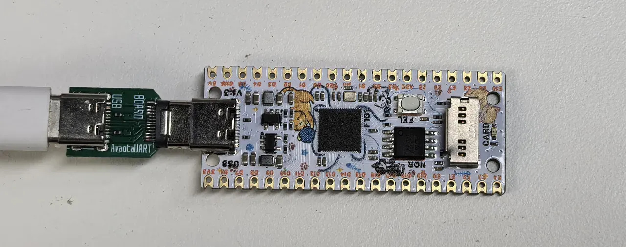
If you do not have an AvaotaUART, connect a generic USB-to-TTL serial adapter as in the table below:
Board pin Signal direction Connect to serial adapter PB0UART1 TX, board transmits RXPB1UART1 RX, board receives TXGNDSignal ground GNDWith the component side up and the USB-C connector at the top,
PB0andPB1are on rows 10 and 11 of the right-hand header, andGNDis on row 2 of the right-hand header; see Pinout for the positions, and before wiring check the schematic for the corresponding hardware revision. The board is powered over USB; connect only the three signal wires from the table to the serial adapter and leave the power pins unconnected, using 3.3 V logic level.
In the serial terminal, select the port the adapter actually uses, set it to 115200 baud, 8N1, no flow control, and open the port before resetting the board to boot the system. 8N1 means 8 data bits, no parity and 1 stop bit. The port name on the host varies with the adapter and the computer, so do not copy someone else’s port name as a fixed value.
Serial input in this package is sensitive to long pasted strings; you can set the terminal’s send delay to about 20 ms per character.
Flashing the full image
Section titled “Flashing the full image”The examples below use xfel. When using rfel, just replace xfel with rfel in the commands.
1. Enter FEL and identify the device
Section titled “1. Enter FEL and identify the device”Hold the FEL button, reconnect the USB data cable, and release it. Then check the chip and flash in the host terminal:
xfel versionxfel spinorAn F101 with chip ID 0x00193700 and a 16 MiB flash should be detected. This step does not need the ddr command. If the device is not found or the chip is reported as unsupported, check the tool version, the connection and the driver as described in FEL common errors before continuing to flash.

2. Write the image and read it back
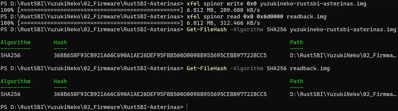
Section titled “2. Write the image and read it back”xfel spinor write 0x0 yuzukineko-rustsbi-asterinas.imgxfel spinor read 0x0 0x6d0000 readback.imgWait for the write and read-back commands to finish normally. The read-back range covers the 0x6d0000 bytes of the full image (7,143,424 bytes).
3. Verify the read-back
Section titled “3. Verify the read-back”Compute the SHA-256 of the original image and of readback.img, and confirm that they match each other and match the value recorded in SHA256SUMS. Pick one of the command groups below according to the host system.
Windows PowerShell:
Get-FileHash -Algorithm SHA256 yuzukineko-rustsbi-asterinas.imgGet-FileHash -Algorithm SHA256 readback.imgLinux:
sha256sum yuzukineko-rustsbi-asterinas.img readback.imgmacOS:
shasum -a 256 yuzukineko-rustsbi-asterinas.img readback.imgThe SHA-256 of this package’s full image is:
368b658f93cb921a66c690a1ae26def95fbb500d0098b955695cebb977228cc5Resolve any error or digest mismatch before booting. A matching read-back shows the image was written correctly; whether the system boots and the examples complete still requires the verification steps that follow.
After boot
Section titled “After boot”Reset and enter the BusyBox shell
Section titled “Reset and enter the BusyBox shell”Confirm the serial terminal is open, release the FEL button, and reset the board from the host terminal:
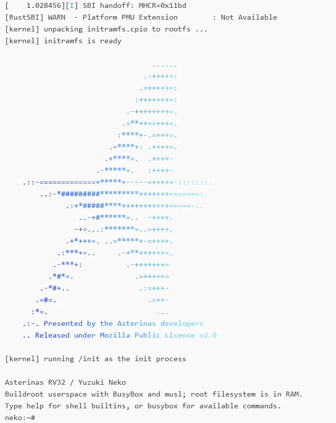
xfel resetThen watch the boot process in the serial terminal. The system loads the image from the SPI NOR, boots and finally reaches a BusyBox shell. The prompt in this package is neko:~#, where commands can be typed. RustSBI logs at WARN level, so its INFO banner is not visible during a normal boot.
Run the nine examples
Section titled “Run the nine examples”In the BusyBox shell, run:
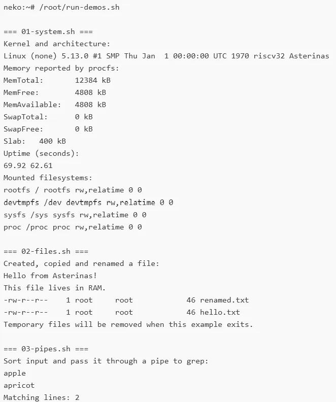
/root/run-demos.shThe following nine examples run in order, showing the basic features of the current port:
| Example | Content |
|---|---|
01-system.sh | Show system, architecture, memory, uptime and mount information |
02-files.sh | Create, copy and rename files in the RAM filesystem |
03-pipes.sh | Combine sort, filter and count commands through pipes |
04-process.sh | Create a child process, wait for it to exit and read its exit status |
05-signals.sh | Send and handle a signal, then continue with the following operations |
06-float.sh | Format and print floating-point numbers |
memory-demo | Anonymous memory mapping, read/write, changing protection attributes and unmapping |
threads-demo | Thread scheduling and synchronization; two threads update the same counter |
ipc-demo | Private memory, pipe communication and process reaping between a parent and child process |
When the run completes you should see:
All 9 Asterinas examples completed.The shell prompt then returns. The Collected child exit status: 7 in the process example is the child exit status the example is designed to produce; it does not mean the whole set of examples failed. The current root filesystem resides in RAM, so changes are not kept after a reboot.
Other notes:
rebootrestarts the system.poweroffstops the system, but the board is still powered over USB and the power is not cut.
File list
Section titled “File list”The repository’s 02_Firmware/RustSBI-Asterinas/ provides the following files:
| File | Purpose | Size (bytes) |
|---|---|---|
syterkit-3bf4f61f.bin | SyterKit with an eGON boot header; initializes RAM and loads the following images | 49,152 |
rustsbi-0.4.1.bin | RustSBI 0.4.1, customized for the Neko RV32 scalar extensions, WARN-level logging | 270,336 |
asterinas.bin | Raw image of the Asterinas RV32 kernel | 2,762,160 |
yuzukineko-rustsbi-asterinas.img | Full boot image: the three above + devicetree + initramfs containing BusyBox | 7,143,424 |
SHA256SUMS | SHA-256 of the four images above | — |
manifest.json | Source versions, Flash layout and verification information | — |
licenses/ | Licenses and third-party notices | — |
Replacing a single component
Section titled “Replacing a single component”Prerequisite: the board already has the full image from this directory installed. Hold FEL and reconnect USB, then check the device with version and spinor first.
In this layout the Flash offsets and RAM load addresses differ; use the NOR offsets below:
| Component | NOR offset | Reserved in this layout | RAM load address |
|---|---|---|---|
| SyterKit | 0x000000 | 64 KiB | 0x00020000 |
| Devicetree (in the full image) | 0x010000 | 256 KiB | 0x40f40000 |
| RustSBI | 0x050000 | 512 KiB | 0x40f80000 |
| Asterinas | 0x0d0000 | 5 MiB, up to the initramfs | 0x40000000 |
| initramfs (in the full image) | 0x5d0000 | 1 MiB | 0x40500000 |
These size limits apply only to this image layout. When building your own, you must also ensure that the entry point, load addresses, devicetree and memory usage are compatible with one another; the binary size alone is not enough. In particular, the memory RustSBI uses at runtime (including BSS, stack and heap) must fall inside its reserved area.
Choose the write commands you need; replacing one component does not require rewriting the others:
xfel spinor write 0x0 syterkit-3bf4f61f.binxfel spinor write 0x50000 rustsbi-0.4.1.binxfel spinor write 0xd0000 asterinas.binAfter writing, read back the corresponding range using the actual file size and verify it. For example, after replacing RustSBI:
xfel spinor read 0x50000 0x42000 rustsbi-readback.bin0x42000 is the size of this package’s RustSBI file (270,336 bytes); for other versions adjust the length to the actual size. Once the read-back SHA-256 matches the written file, run xfel reset.
Component versions
Section titled “Component versions”From manifest.json:
| Component | Version / commit | Notes |
|---|---|---|
| SyterKit | Based on 3bf4f61f | Neko SPI NOR loader and Asterinas handover; not an unmodified upstream build |
| RustSBI | 0.4.1 (4068e0d0) | Color-removal patch, Neko RV32 scalar target, WARN logging |
| Asterinas | Based on db0d7958 | Neko RV32 port and BusyBox integration |
| BusyBox | 1.37.0 | Static RV32GC ILP32D musl build |
| musl | 1.2.5 |
Verification record
Section titled “Verification record”Verification date 2026-09-12, board Yuzuki Neko F101-S3: flash read-back matched the image SHA-256; SPI NOR boot reached the BusyBox shell; the nine examples passed.
License
Section titled “License”The firmware and its third-party software follow their own licenses; the repository’s CC0 statement does not apply to them. The license texts and sources for the four components are in the repository’s licenses/README.md.